| |
· As you may noticed, all the mentioned models run in a 2D environment. However, nodes move in a 3D space in the real world. This concernment becomes more important in large maps where there is a network considerable altitude. This model, as a complex model, gets a model and a 3D map as its parameters and tries to find the altitude of a node in the map. 3D map as the base map in 3D model has its own parameters:
- gridsize specifies maximum width and height of grids of the 3D map. Note that grid points will be always on the map and have zero altitude by default. You can change their Z value like user specified points. See the points section.
- CachePrecision: The 3D map does not calculate the Z position of a node if it was calculated before. CachePrecision parameter configures the process of finding the previous node’s Z position. If a point in the map with CachePrecision distance from current node’s position has a calculated Z factor, the 3D map will return its value; otherwise, it will calculate the Z factor and adds it to the cache.
- Points: Each point defines a point in the 3D space which has x, y, and z values. As the grid points will be always present in the map, you can only change their z parameter’s value by defining a point just on the grid point coordination. Non-grid points are also supported.
Note that in order to resimulate the simulation scenario, there is a file parameter, “mapsetting output”, which tries to export the 3D map settings. Set the output file address if want to use 3D resimulation.
The following paragraphs will describe how this model works. You may skip these paragraphs if you do not want to know the details.
In the initialization step, after loading the points and setting the grid points, the 3D map creates blocks using each four grid points. In order to find the Z value of the position of a node, the following steps will run:
- Check if the current node is on a predefined point;
- Check if the current node is near enough to a cached position;
- Find the triangle that surrounded the current point (The grid points helps restrict the computation overhead of this process.)
- Check if all the triangle vertices have equal Z, use it
- Otherwise, create a 3D plane using the three points and find out the z value
In the current step, I use the 2D map editor for this model. Each point in the map has its own map handle in the map editor. While the grid points  could not be dragged in the map, you can add, remove, or move additional points could not be dragged in the map, you can add, remove, or move additional points  . Each 3D point has a Z parameter which can be configured using the handle configuration panel. Note that the size of the 3D map is determined by the size of 2D map in the internal model and the offset handle cannot be moved. Besides, neither an additional point nor a grid point with non-zero Z parameter can be out of the map. . Each 3D point has a Z parameter which can be configured using the handle configuration panel. Note that the size of the 3D map is determined by the size of 2D map in the internal model and the offset handle cannot be moved. Besides, neither an additional point nor a grid point with non-zero Z parameter can be out of the map.
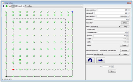
ThreeDizer model Map Editor window (using Random Walk)
NOTE: in the current implementation the horizontal speed of a node does not depend on the slope of the ground. I know that it may make threeD model useless, but it is just the start.
3D Resimulator uses java3d package to create a 3D environment. Therefore, you should have installed the package. Initially, you must select the trace file which contains Z positions for nodes and the 3D map configuration file exported in the simulation process.
Click on “Start” menu item to run the simulation. You can move forward and backward using up and down arrow keys, turn left and right using left and right arrow keys, and turn up and down using page up and page down keys. Use home key to reset the camera position. The following paragraphs explain how the ground map created using the user-defined points.
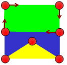
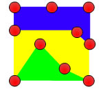
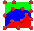
The java3d package gets a list of strips, triangulates them, and puts the triangles together to create a surface. Our algorithm tries to create these strips such that the resulting triangles would be similar to what the 3D model is used in mobility generation. In each block, created based on the map configuration, the implemented algorithm tries to walk clockwise on the block and create strips. Figure a shows the clockwise walk and Figure b and c presents some sample strips. As the strip creation algorithm is a complex one, I will not present it here. Refer to the development document to find out about it.
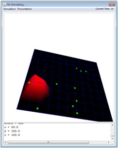
A preview of 3D resimulator window |
|